solidworks flow simulation boundary conditions
It is related to the geometry of the model assuming the boundary conditions are done. Right click on the outflow boundary surface and select.

Pin On Ansys Workbench Tutorials
Button in the.

. I am currently running SolidWorks Premium 2009 with Flow Simulation 2009. When checked Flow Simulation automatically checks the internal flow boundary conditions specified in Boundary Conditions. Window and select.
At the boundaries of an internal flow analysis in Flow Simulation one must specify the pressure from the outside fluid as either Static or Total depending on how the pressure was measured. It uses the SOLIDWORKS modeling engine to define the physical geometry and then the Flow Simulation environment defines boundary. Select the Face corresponding to the outflow boundary.
However when I click on the face of the lid I am trying to set the boundary condition I come up with the error. Portion of the. Tools Flow Simulation Insert Transferred Boundary Conditions.
SR By Sanjay Ramlall 052119. The water tank you see here has some jets on the inside corners highlighted yellow and along some of the walls. Flow Simulation analysis tree.
The SolidWorks Flow Simulation modifications to the Launder-Spalding wall function approach for specifying the wall boundary conditions for the Navier-Stokes equations are called Enhanced Turbulence Modeling ETM. For fluid mixing all of the fluids being mixed must be in the. Utilize Symmetry boundary conditions on parts with symmetric inlets and outlets to save time and effort in Simulation Flow.
To apply symmetry. I am performing flow analysis on a low speed low pressure high flow turbine pump and feel i have the entire concept of simulation wrong. For instance this option warns you if the mass flow rate is unbalanced.
If the user neglects to assign a boundary condition at an opening then the opening would be analogous to encountering a vacuum. Solidworks Flow simulation Boundary condition question image included 1. A mass flow rate imbalance can occur.
Other types of structural loads are available via special functions like importing loads from SolidWorks Flow Simulation or SolidWorks Motion. SOLIDWORKS Flow Simulation allows a designer to take advantage of. SOLIDWORKS Flow Simulation can be configured for symmetry periodicity or even planar flow to speed up the solution or to increase the mesh quality without impacting the accuracy of the flow results.
Set the Computational Domain to symmetry and adjust. Sedan car Perodua Bezza by using two different CFD simulation software which are SolidWorks oftware used the same boundary condition and setup except for the type of flow used in the simulation in order to obtain a fair result. Learn about some features and differences of the Real wall and Ideal wall boundary condition in SOLIDWORKS Flow SimulationQuickTips video presented by T.
Arrows from the face indicate the flow direction. Applying Boundary Conditions in a Flow Study in SolidWorks. And select Insert Boundary Condition.
SOLIDWORKS Flow Simulation allows the use of non-newtonian fluids gases real gases and liquids. Click the CD feature in the tree to show arrowshandles on the screen to re-position the cube over where you want to focus your Zooming study. Resize your Computational Domain CD.
SOLIDWORKS Flow Simulation 2016 has capabilities for solving various flow and thermal problems. Usually when you receive the SOLIDWORKS Flow Simulation Error. Hey everyone I need some help with the boundary conditions of this problem.
A load or restraint is applied by the corresponding PropertyManager accessible by right-clicking the Fixtures or External Loads folder in the Simulation study tree or by clicking Simulation LoadsFixture. SOLIDWORKS Flow Simulation creates mirrored results for symmetric studies. Applying Boundary Conditions in a Flow Study in SolidWorks.
The velocity inlet used for this project is 3056 ms and the turbulence model selected is standard k-ε. In order to use the symmetry in flow simulation both the geometry and the boundary conditions should be symmetric. Hello I am seeking some general guidance on flow simulation in solidworks.
Symmetry and periodic boundary conditions in SOLIDWORKS Flow Simulation are used to reduce the size of the flow problem thereby reducing analysis run time. This question has a validated answer. If the rotating region is centered between an inlet and outlet it is recommended the inlet condition is a flow rate or a pressure boundary condition and the outlet condition is a pressure boundary condition.
Flow Simulation Boundary Conditions. SOLIDWORKS Flow Simulation is an intuitive Computational Fluid Dynamics CFD solution embedded within SOLIDWORKS 3D CAD that enables you to quickly and easily simulate liquid and gas flows through and around your designs to calculate product performance and capabilities. Temperature may affect the fluid properties.
Click on the. SOLIDWORKS Flow Simulation with less than 8 hours of training. The SolidWorks Flow Simulation Modified k-Ε Turbulence Model.
SOLIDWORKS Flow Simulation offers a wizard to direct the setup including the selection of material properties. Face to Apply Inlet Boundary Condition. Flow Simulation Boundary Conditions.
Face is not laying on the boundary between the solid and fluid region. In SolidWorks Flow Simulation I am trying to create boundary conditions such that I can run an internal flow analysis. The mixing of fluids is a phenomenon that needs to be accurately modeled in order to understand the behavior of the different fluids involved as well as understanding the rate that the mixing happens.
Sets the temperature of the incoming fluid. Sets the face used for the inlet boundary. Flow Simulation will automatically calculate the inlet and outlet values at the rotating region.
JT By Jacob Trieu 122210. Although these two computational domain boundary conditions are set up by editing the default computational domain they both are very different. SOLIDWORKS FloXpress remembers the initial selection in later calculations.
As an example the following picture shows a piston valve in which the water enters through the inlet in the center of the valve. The starting point of any heat transfer analysis is to define the overall boundary conditions of the problem. Its structure is shown schematically in Figure1.

Pin On Ansys Workbench Tutorials
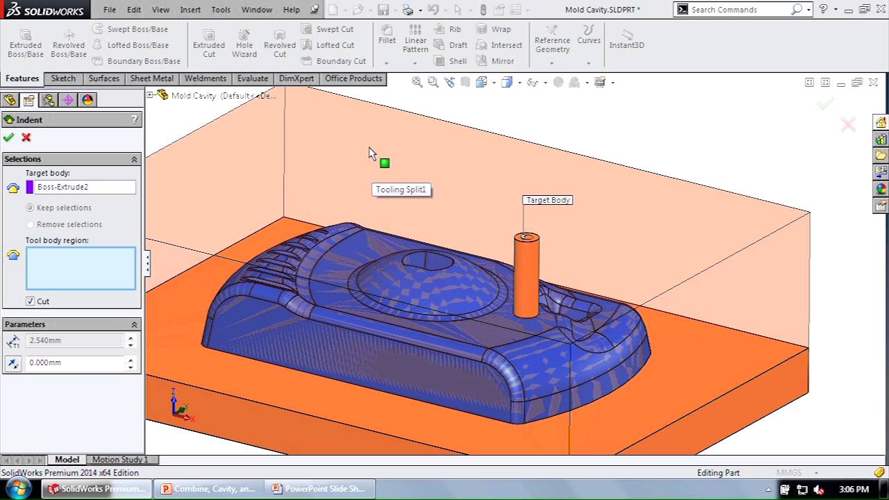
Solidworks Tips Tricks Combine Cavity Indent What S The Difference Solidworks Solidworks Tutorial Cavities

Pressure Drop In Cfd Tool In Solidworks Flow Simulation Http Blogs Solidworks Com Solidworksblog 2013 10 Relax And Reduce Hair Loss We Have The Solution For

Catia Solidworks Jet Fighter Design Flow Simulation Tests By Mohamed Hedi K

What Is Center Of Gravity Centroid How To Find Center Of Gravity In Ansys Ansys Finite Element Finite Element Analysis

Pin By Harlylichuzz Cadcamcorner On Work Solidworks Solidworks Tutorial Solid Works

Aerodynamic Analysis With Solidworks Flow Simulation Image Aerovelo Fast Bikes Concept Design Nature Words

Slame Studio Solidworks Tutorial Berbahasa Indonesia Flow Simulation Solidworks Tutorial Solidworks Simulation

Cfd Simulation Simulation Technology
This Video Explains Axisymmetric Analysis Of Pressure Vessel Using Ansys Mapdl It Briefs About Axisymmetric Mo Finite Element Analysis Analysis Finite Element

Draw An Aerofoil Using Imported Coordinate Data Points In Solidworks Tut Solidworks Solidworks Tutorial Coordinates

Draw An Aerofoil Using Imported Coordinate Data Points In Solidworks Tut Solidworks Solidworks Tutorial Coordinates

This Video Explains Oil Gas Field Lifecycle Development Through Its Various Phrases Like Access To Site Appraisal Wells Develo Oil And Gas Development Oils

This Video Explains The 1d Beam Topside Module Structure Modeling Using Ansys Workbench Design Modular It Briefs Introducti Workbench Designs Design Workbench

Aquapini And Walipini Open Source Hub Open Source Solidworks Aquaponics

Wave Generation Simulation Flow 3d Cfd Software Cfd Simulation Types Of Waves Simulation

Autofem Analysis Is The Finite Element Analysis Software The Main Feature Of The System Is Its Deep Integration Finite Element Finite Element Analysis Abaqus

Effect Of Boundary Condition In Thermal Analysis Using Ansys Analysis Ansys Structural Analysis

Top 5 Reasons Why You Should Try Cfd Within Solidworks Checkout The Below Infographic And Share Solidworks Computational Fluid Dynamics Engineering Courses